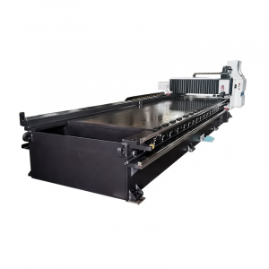


- Product introduction

Rongwin produces various types of plate bending machines, such as mechanical
three-roller symmetrical plate bending machine, hydraulic three-roller
symmetrical plate bending machine, upper-roller universal plate bending
machine, four-roller plate bending machine, etc. The plate rolling machine is a
shaping machine for continuous point bending of plates. It has the function of
rolling O-shaped, U-shaped, multi-segment R and other shapes of plates. Meet
the needs of different customers.

Ⅰ. Main Function
This device is three rollers symmetrical mechanical rolling machine. It is used to
Bend steel into drums shape with different diameters. And it is widely used in
boiler industry, chemical industry, mine industry, building industry, shipbuilding
industry.
Ⅱ. Main structure and work principle
A.This machine is symmetrical rolling machine, down up roller and then let up
and down rollers do opposite roll to bend steel plate.
B. This machine composed of two parts those are working part welded in whole
chassis and moving part. Working part composed of left and right bearing base,
one up roller, two bottom rollers (the material of the three rollers is 45#steel and
do heat treatment),lifting screw and turbine and other accessory parts. Down
rollers drive up roller to move, up roller can do up and down move by height way.
Drive part composed of main motor, main speed reducer and other accessory parts.
C. Bottom rollers were drove by main motor through main speed reducer, output
spindle of main speed reducer driven to two down rollers by one group gears, the
revolve direction of rollers adjusted by main motor.
D. Upper roll lifted by accessory motor through vice speed reducer drive worm
and worm wheel mechanism of right/left rolls bearing base. That to let the lifting
pole do up and down move.
E. Unloading device is designed to remove the workpiece after drums bended into
shape. Before unloading the upper rolls move to up limit position, the balance
device on upper rolls ends hit upper rolls ,draw out the spindle of the pin ,then
to remove the workpiece.

Ⅴ. Supply range and packing
A.Body part
Up and bottom rollers devices, main motor device, balance device, rack of
machine, base and so on.
B.Electrical control system
C.Lubrication system
D.Components related to the whole machine
E.Spare part provide by machine
F.Technical files provide by machine
a. Install drawing, electronic drawing, reference ,certificate, container loading list.
b. Inspection of material, report of heat treatment, material machine test and so on.

Upper Roll Universal Rolling Machine Technical Characteristics
1.Drum-shaped upper roller, lower roller and lower roller are coordinated and adjusted for
high-precision product straightness.
Drum-shaped upper roller is adopted, and the upper roller drum-shaped preset amount is
generally 70% of the uniform load of the roller to preset; the lower roller with smaller
diameter is supported by the lower part of the lower roller with adjustable upper and lower
rollers. According to the load of the rolled product, the idler under the lower roller is
adjusted to greatly improve the straightness of the product.
2.Rear bending and rolling, high-precision product roundness.
The upper roll universal rolling machine adopts rear bending (the feeding direction of the
plate is opposite to the moving direction of the upper roll), the upper roll is pressed down
while the lower roll rotates, continuously bending, and the end of the plate is directly
pre-bent. , To avoid the front bend angle, and can control the length and shape of the
remaining straight sides.
Generally, the three-roll asymmetric type adopts forward bending. First, the two ends of
the sheet are pre-bent, and then symmetrically rolled into shape. Skilled operators are
required. The product has a back angle and the shape of the remaining straight edges is
difficult to control.
3.Reduce the amount of product misalignment.
The upper roll universal bending machine has adopted the following measures to reduce the
amount of product misalignment:
1)The bending machine adds a longitudinal alignment device;
2)The dimensional accuracy and shape tolerance of the center distance between the two
lower rollers and the two lower rollers are used as key process control;
3)The synchronous electro-hydraulic combination of the upper roller uses a feedback system
to automatically level.
Displacement sensor detection, the stroke preamplifier signal of the upper roller cylinder
is amplified, the industrial control computer compares, the high and low levels are given to
the programmable controller, and the electromagnetic reversing valve solenoid at both ends
of the upper roller is controlled, constant feedback comparison, synchronous precision
control Within ±0.15mm.

2.Lower roller and horizontal moving device
The lower roller device is composed of the lower roller, the lower roller bearing
seat, the lower roller input gear, and the lower roller sliding bearing.
The material of the lower roll is alloy steel 42CrMo, after rough machining,
quenching and tempering treatment: HB240-280, roll surface quenching:
HRC40-52, according to JB/ZG4289-86 roll steel standard, static safety factor
of 3, rigidity conforms to (1/700~ 1/1000) L
L—refers to the distance between the center lines of the racks on both sides.
The sliding bearing of the lower roller is made of SF-1 self-lubricating composite
material.
The horizontal moving device is powered by the horizontal moving motor, and
the upper roller device is driven to move horizontally through the worm gear box,
worm gear and screw nut mechanism, so as to realize the asymmetric rolling of
the plate.
The main drive of the lower roller provides power through the main drive output
gear, the lower roller input gear, and the open transmission torque to the lower
roller.
3.Support roller device
The supporting roller device is composed of supporting roller, screw mother
screw mechanism, inclined wedge mechanism and so on.
The roller is made of 45 steel, quenched and tempered, and the hardness is
HB190~220.
The surface hardness of the roller is lower than that of the lower
roller, and the surface is turned with spiral grooves, which effectively prevents
the oxide scale and impurities of the lower roller from damaging the working
surface of the lower roller. .
There are a group of four rollers in each group, which can be adjusted up and
down according to the load size of the rolled sheet specification.
4.Main drive
The main transmission device is composed of a main motor, a cylindrical gear
reducer and a coupling.
5.Tipping device
The tipping device is composed of a ram, a tipping cylinder, etc.
The piston rod of the overturned cylinder is chrome-plated.
The overturning device facilitates the removal of the product along the axial
direction of the roller.
6.Fixed and overturned side frame and chassis
The fixed and overturned side frame and chassis are welded parts of steel plates,
which are annealed after welding to remove stress and shot peened.
The fixed, overturned side frame is used to house the two main cylinders.
The chassis adopts a frame structure, with high torsion resistance section
coefficient, few anchor bolts, and convenient installation and debugging.
Ⅱ. Details
一、Hydraulic system
The hydraulic system consists of hydraulic pumps, valve blocks, fluid
connections, hydraulic accessories, etc. The hydraulic valve adopts superimposed
valve series, with simple pipeline layout and convenient maintenance and
debugging.
The system consists of three circuits, overpressure protection and pressure
regulation circuit, synchronization circuit, and speed circuit.
The pressure regulating circuit regulates the working pressure of the system
through the main relief valve.
The working pressure of the system is 20MPa.
Synchronous circuit uses a shunt throttle valve to synchronize the rising and f
alling coarse steps of the upper roller, and the throttle valve adjusts up and down;
the displacement sensor detects that the positioning accuracy of the upper roller
synchronization is ±0.15mm.
The speed loop controls the overturning and resetting of the machine on the
overturned side, and adjusts the loop throttle speed through the throttle valve.
The rising and falling of the upper roller are respectively provided with overflow
valves for pressure limit protection.

二、Electrical control system
1.Overview.
The electrical control system of the equipment consists of an electrical control
cabinet, an operating console, and a handheld button box. The power supply is
three-phase four-wire system 380V/50Hz.
The control circuit adopts PLC programmable controller system, with few relays,
reliable action and long life.
The control cabinet is equipped with all control buttons, indicator lights,
programmable displays, etc. to complete the rolling process of the product to
monitor the rolling working status and operation control of the whole machine.
2.Various protection.
Each motor has a corresponding circuit breaker for over-current short-circuit
protection;
Each motor has a corresponding thermal relay for overload protection;
The horizontal movement of the upper roller and the lifting of the supporting
roller have corresponding limit switches for limit protection;
The overturning and resetting of the overturning cylinder are respectively
equipped with upper and lower limit switch limit protection;
The main power circuit breaker has a shunt release, and there are "emergency
stop" buttons on the console and the side of the overturned support to cut off the
main power remotely.
3.Various interlocks.
After the tipping frame is fully reset, the upper roller lifting, moving forward and
backward, the lower roller forward and reverse, and the supporting roller lifting
and other actions can be carried out (use the "tilt frame reset" limit switch for
detection);
When the upper roller is in the upper position, the upper roller moves horizontally,
and the overturned side falls alone cannot be carried out (the "upper roller upper
position" limit switch is used for detection);
When the working pressure of the upper roller pressure relay is greater than 1/3P,
the upper roller cannot move back and forth, and the supporting roller cannot rise
or fall (the pressure relay is used for detection).
4.Fault indication.
When the lower roller motor, horizontal movement motor, and idler motor are
overloaded, the fault indicator will prompt, and help information can be obtained
on the display;
When the PLC fails, the fault indicator will indicate.

The machine adopts the four-roller structure with the upper roller as the main drive,
providing the plates bending with torque through the engagement between the gear of the
moderator and the gear of the upper roller. The lower roller makes vertical movements and
imposes a force on the piston through the hydraulic oil in the hydraulic cylinder so as to
clamp the plate tight. Side rollers are arranged on the two sides of the lides of the lower roller,
and make inclining movement along the guide rail, and provide drive through the screw,the
nut,the worm and the lead screw.
Ⅰ. Main Function
The W12 four-roller plate bending machine is a metal plate bending and
correction machine, specially used for the forming and bending of metal plates.
The pre-bending and curling of cylindrical and arc-shaped workpieces of various
specifications can be completed after one feeding, and rough shaping of metal
sheets can also be performed. It is widely used in shipbuilding, boiler, aviation,
bridge, hydropower, chemical industry, metal structure and machinery
manufacturing industries.
Machine tool usage environment: temperature 5-40°, humidity less than 80%;
power supply 380V50Hz
Ⅱ. Overview of the main structure
This machine is a four-roller plate bending machine. Its structure is shown in
Figure 1. The upper roller is the driving roller, the lower roller and the side roller
are driven rollers. The position of the upper roller is fixed. The lower roller can
move up and down. The upper roller is mechanically driven. The roller drive is
driven by the gear engagement between the upper roller and the lower roller, and
the rotation of the side roller is driven by the friction between the steel plate and
each roller. The lifting and lowering of both ends of the lower roller is caused by
the oil cylinder. The turning and resetting of the bearing body on the front side of
the upper roller are performed by an oil cylinder. Each roller bearing body and oil
cylinder are installed in the frame at the left and right ends.
The left and right frames are the main body of the four-roller plate bending
machine. They adopt a welded structure and are installed on the overall welded
bottom. All operations are performed on the operating system.
Compared with the symmetrical three-roller plate bending machine, this four-roller
plate bending machine can directly pre-bend the end of the plate without using
other equipment molds, and the remaining straight edge is smaller; compared with
the asymmetric three-roller plate bending machine, it can The sheet is rolled into
workpieces without turning around. This not only improves efficiency and ensures
the quality of workpieces, but also makes the process simple, easy to operate, and
reduces the labor intensity of workers.